Device description
|
|
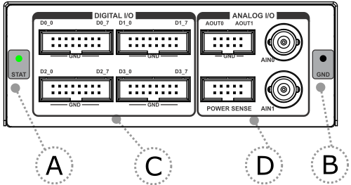
The front face features:
A – The indicator light provides the status of the hardware - At power on the LED will blink 5 times with a frequency of 1Hz, then it will stay ON continuously. If LED remains blinking or it doesn't blink on after power ON, please contact support.
B – The grounding socket (marked GND). It represents the GND potential of the BlueBox and its usage is optional. By default no connection to this socket is required. The grounding socket is suitable for a 2mm Multi Contact Plug (also known as a Banana Plug).
Note that the grounding connection between the BlueBox and the Target microcontroller development board must be established through the iC7max/iC5700 grounding socket. Refer to the iC7max or iC5700 Hardware User Manual for more details on this grounding.
C – Four Digital I/O connectors (16-pin IDC connector 2.54 mm) each providing 8 signals: D0, D1, D2, D3
D0 |
D1 |
D2 |
D3 |
D4 |
D5 |
D6 |
D7 |
|---|---|---|---|---|---|---|---|
GND |
GND |
GND |
GND |
GND |
GND |
GND |
GND |
D – ANALOG I/O connectors
AOUT0, AOUT1 – Two analog outputs available on 10-pin IDC connector 2.54 mm
AIN0, AIN1 – Two analog inputs available on BNC connectors, which can be connected using standard oscilloscope probes.
AOUT0 |
AOUT0 |
|
AOUT1 |
AOUT1 |
|---|---|---|---|---|
GND |
GND |
GND |
GND |
GND |
Power Sense (Power Probe)– 10-pin IDC connector 2.54 mm
RS+ |
AIN |
GND |
|
CTL |
|---|---|---|---|---|
RS- |
|
GND |
|
|
For Power Probe use cases refer to ADIO Use cases overview in winIDEA Help.
|
All CAN and LIN signals are isolated from the GND. |

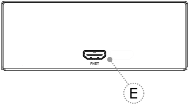
The rear face features the remaining connector:
E – FNet Port
|
Although it looks similar to the HDMI interface, the FNet Port is not compatible with HDMI or any HDMI accessories. Connecting TASKING hardware to the HDMI devices will damage the hardware and will render the TASKING hardware warranty void. |