Device description
|
|
|

A – 10-pin DAP connector, with the following pinout:
Signal Direction |
Signal Description |
Signal |
Pin |
Pin |
Signal |
Signal Description |
Signal Direction |
|---|---|---|---|---|---|---|---|
I |
Reference Voltage |
Vref |
1 |
2 |
DAP1 |
DAP Data |
I/O |
|
Ground |
GND |
3 |
4 |
DAP0 |
DAP Clock |
O |
|
Ground |
GND |
5 |
6 |
DAP2 |
Optional 2nd Data Pin |
I/O |
|
Not Connected |
NC |
7 |
8 |
nTRST/DAPEN |
Optional 3rd Data Pin |
I/O |
|
Ground |
GND |
9 |
10 |
nRESET |
Reset |
O |
10-pin DAP pinout
B – 10-pin DAPE connector, with the following pinout:
Signal Direction |
Signal Description |
Signal |
Pin |
Pin |
Signal |
Signal Description |
Signal Direction |
|---|---|---|---|---|---|---|---|
I |
Reference Voltage |
Vref |
1 |
2 |
DAPE1 |
DAP Data |
I/O |
|
Ground |
GND |
3 |
4 |
DAPE0 |
DAP Clock |
O |
|
Ground |
GND |
5 |
6 |
DAPE2 |
Optional 2nd Data Pin |
I/O |
|
Not Connected |
NC |
7 |
8 |
DAPEN/DAP3 |
Optional 3rd Data Pin |
I/O |
|
Ground |
GND |
9 |
10 |
NC |
Not Connected |
|
10-pin DAPE pinout
Signal direction definition:
O – Output from the Active Probe to the target microcontroller
I – Input to the Active Probe from the target microcontroller
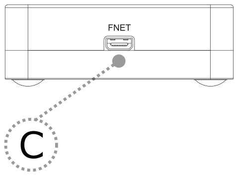
C – FNet Micro connector, that connects the Active Probe to the iC7max or iC5700. The FNet Micro cable is delivered with the Active Probe.
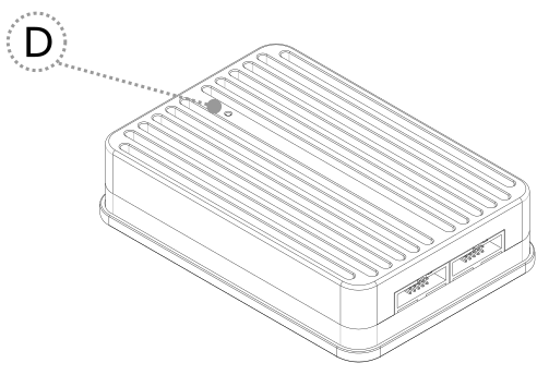
D – The indicator light provides the status of the Active Probe as follows:
|
Permanently green – Powered on and ready to use. |
|
Blinking green – Establishing connection with the BlueBox. |
|
Blinking blue – Reprogramming SPLASH. |
|
Permanently magenta – Golden image loaded and ready to use. |


|
Use only original TASKING accessories for powering and connecting with the iC7max/iC5700. Consult with TASKING before attempting to use any other accessory. |