Device description
|
|
|
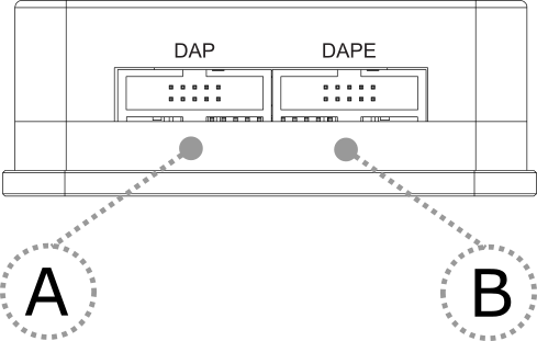

A – 10-pin DAP connector, with the following pinout:
Signal Direction |
Signal Description |
Signal |
Pin |
Pin |
Signal |
Signal Description |
Signal Direction |
|---|---|---|---|---|---|---|---|
I |
Reference Voltage |
Vref |
1 |
2 |
DAP1 |
DAP Data |
I/O |
|
Ground |
GND |
3 |
4 |
DAP0 |
DAP Clock |
O |
|
Ground |
GND |
5 |
6 |
DAP2 |
Optional 2nd Data Pin |
I/O |
|
Not Connected |
NC |
7 |
8 |
nTRST/DAPEN |
Optional 3rd Data Pin |
I/O |
|
Ground |
GND |
9 |
10 |
nRESET |
Reset |
O |
10-pin DAP pinout
B – 10-pin DAPE connector, with the following pinout:
Signal Direction |
Signal Description |
Signal |
Pin |
Pin |
Signal |
Signal Description |
Signal Direction |
|---|---|---|---|---|---|---|---|
I |
Reference Voltage |
Vref |
1 |
2 |
DAPE1 |
DAP Data |
I/O |
|
Ground |
GND |
3 |
4 |
DAPE0 |
DAP Clock |
O |
|
Ground |
GND |
5 |
6 |
DAPE2 |
Optional 2nd Data Pin |
I/O |
|
Not Connected |
NC |
7 |
8 |
DAPEN/DAP3 |
Optional 3rd Data Pin |
I/O |
|
Ground |
GND |
9 |
10 |
NC |
Not Connected |
|
10-pin DAPE pinout
C – The indicator light provides the status of the Active Probe as follows:
|
Permanently green – Powered on and ready to use. |
|
Blinking green – Establishing connection with the BlueBox. |
|
Blinking blue – Reprogramming SPLASH. |
|
Permanently magenta – Golden image loaded and ready to use. |


D – mDIO port with the marked Pin1 on the housing
mDIO port provides two digital signals, which can interact with the embedded target. Each can be configured either for input or output operation.
mDIO port pinout |
mDIO port on the Active Probe |

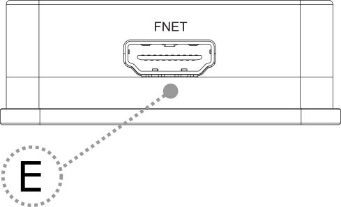
E – FNet connector, that connects the Active Probe to the iC7max or iC5700. The FNet cable is delivered with the Active Probe.
|
When powering on the system, switch the BlueBox on before powering on the target. When powering down the system, power off the target before powering off the BlueBox! Use only original accessories for powering and connecting with the BlueBox. Consult with technical support before attempting to use any other accessory. |