Conversion board configuration
IEA-SPC58NH-BGA302
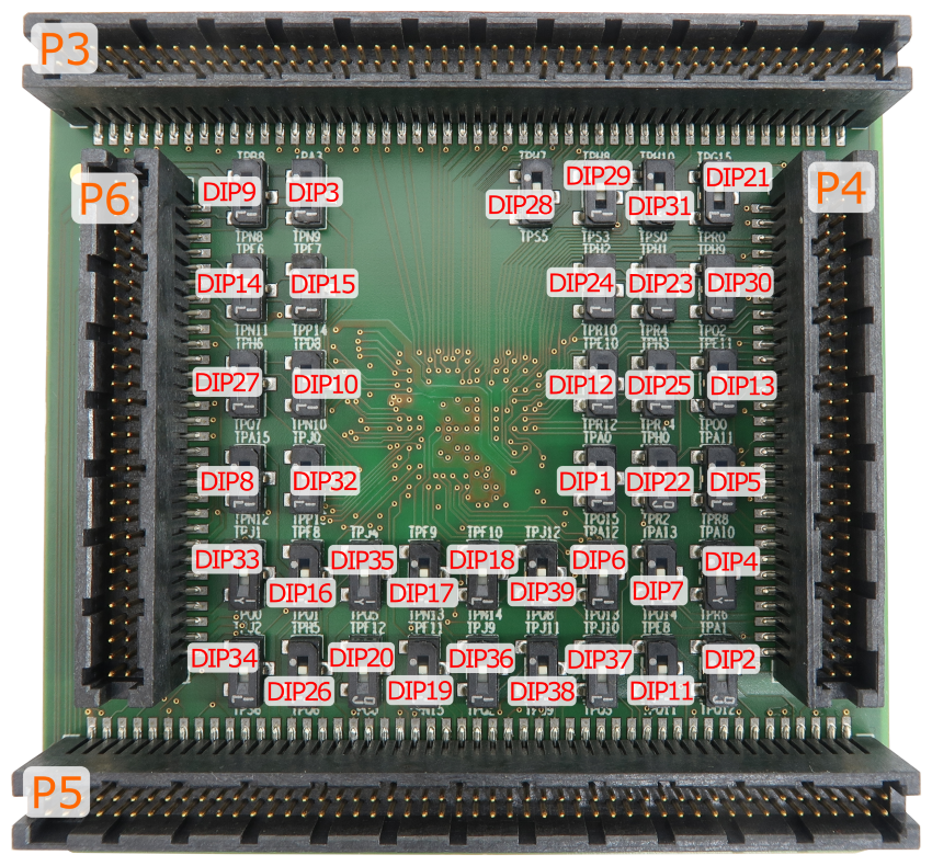
Conversion board IEA-SPC58NH-BGA302 consist of 39 DIP switches, which define which alternate port is connected to a specific CPU pin.
With the original microcontroller in the BGA302 package, this is configured through the application software. However, when using the Emulation Adapter based on the BGA386 "superset" device, this configuration has to be performed manually through jumpers DIP1-DIP39 since for some reason each of the alternate ports is routed to an individual physical pin on the BGA386 device without the possibility for controlling routing by means of application software.
For example, with the original microcontroller in the BGA302 package, the application software can route either port PQ[15] or port PA[0] to pin A17. However, with the “superset” microcontroller in the BGA386 package, port PQ[15] is fixed connected to pin L22 and port PA[0] to pin B18. Hence with the Emulation Adapter you can define with the jumper DIP1 whether port PQ[15] or port PA[0] is routed to target pin A17 on the 302-pin conversion board.
|
Set all the DIPs accordingly to exactly match with your application software configuration. Any mismatch in configuration will yield application not operating properly! |
DIPs are by default in position 1-2 (enabled).
Following picture shows DIPs location on the top side of the conversion board:
DIP |
302-pin CPU Pin Number |
DIP position 1-2 (Default) |
DIP position 2-3 |
|---|---|---|---|
DIP1 |
A17 |
PA[0] |
PQ[15] |
DIP2 |
A18 |
PA[1] |
PQ[12] |
DIP3 |
W16 |
PA[3] |
PN[9] |
DIP4 |
B16 |
PA[10] |
PR[6] |
DIP5 |
A15 |
PA[11] |
PR[8] |
DIP6 |
C19 |
PA[12] |
PQ[13] |
DIP7 |
B17 |
PA[13] |
PQ[14] |
DIP8 |
W18 |
PA[15] |
PN[12] |
DIP9 |
Y15 |
PB[8] |
PN[8] |
DIP10 |
Y16 |
PD[8] |
PN[10] |
DIP11 |
D20 |
PE[8] |
PQ[11] |
DIP12 |
B14 |
PE[10] |
PR[12] |
DIP13 |
B15 |
PE[11] |
PO[1] |
DIP14 |
Y17 |
PF[6] |
PN[11] |
DIP15 |
W17 |
PF[7] |
PP[14] |
DIP16 |
U19 |
PF[8] |
PQ[1] |
DIP17 |
P20 |
PF[9] |
PN[13] |
DIP18 |
P19 |
PF[10] |
PN[14] |
DIP19 |
R20 |
PF[11] |
PN[15] |
DIP20 |
R19 |
PF[12] |
PO[0] |
DIP21 |
E14 |
PG[15] |
PR[0] |
DIP22 |
D15 |
PH[0] |
PR[2] |
DIP23 |
D14 |
PH[1] |
PR[4] |
DIP24 |
E13 |
PH[2] |
PR[10] |
DIP25 |
A14 |
PH[3] |
PR[14] |
DIP26 |
T20 |
PH[5] |
PQ[6] |
DIP27 |
T17 |
PH[6] |
PQ[7] |
DIP28 |
D11 |
PH[7] |
PS[5] |
DIP29 |
D12 |
PH[8] |
PS[3] |
DIP30 |
A13 |
PH[9] |
PO[2] |
DIP31 |
D13 |
PH[10] |
PS[0] |
DIP32 |
Y18 |
PJ[0] |
PP[15] |
DIP33 |
Y19 |
PJ[1] |
PQ[0] |
DIP34 |
V20 |
PJ[2] |
PS[6] |
DIP35 |
T19 |
PJ[4] |
PQ[5] |
DIP36 |
R17 |
PJ[9] |
PQ[2] |
DIP37 |
P16 |
PJ[10] |
PQ[3] |
DIP38 |
P17 |
PJ[11] |
PQ[9] |
DIP39 |
N17 |
PJ[12] |
PQ[8] |
IEA-SPC58NH-TQ176
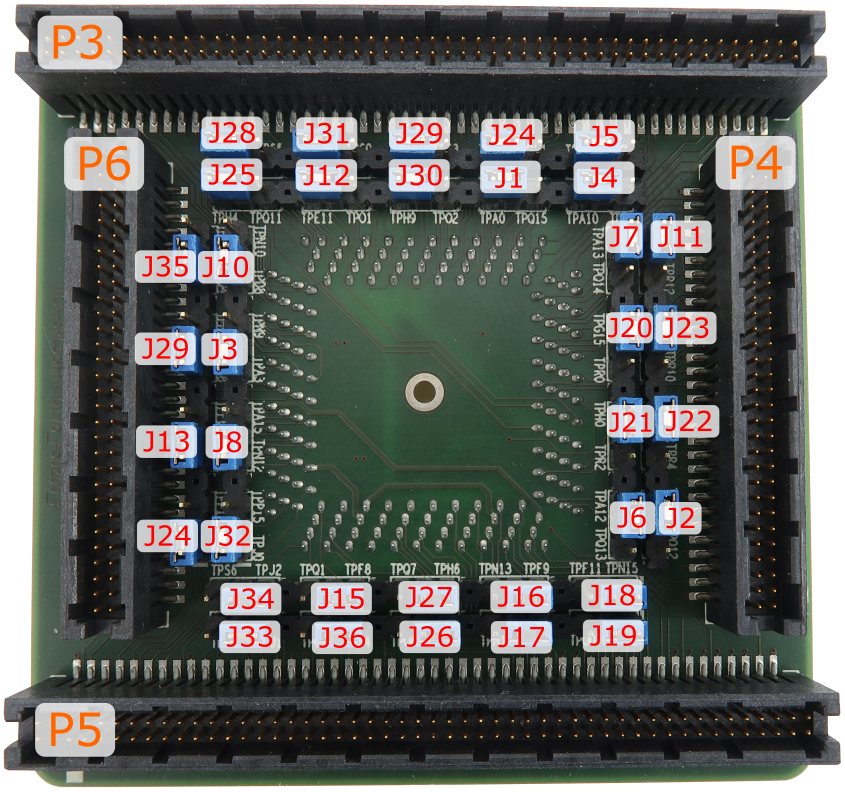
Conversion board IEA-SPC58NH-TQ176 consist of 36 jumpers which define which alternate port is connected to a specific CPU pin.
With the original microcontroller in the QFP176 package this is configured through the application software. However when using the Emulation Adapter based on the BGA386 "superset" device, this configuration has to be performed manually through jumpers J1-J36 since for some reason each of the alternate ports is routed to an individual physical pin on the BGA386 device without the possibility for controlling routing by means of application software.
For example, with the original microcontroller in the QFP176 package, the application software can route either port PQ[15] or port PA[0] to pin 137. However, with the “superset” microcontroller in the BGA386 package, port PQ[15] is fixed connected to pin L22 and port PA[0] to pin B18. Hence with the Emulation Adapter you can define with the jumper J1 whether port PQ[15] or port PA[0] is routed to target pin 137 on the 176-pin conversion board.
|
Set all the jumpers accordingly to exactly match with your application software configuration. Any mismatch in configuration will yield application not operating properly! |
Jumpers are by default set to position 1-2.
Following picture shows jumpers location on the top side of the conversion board:
|
Silkscreen on PCB revision A does not reflect correct jumper signal names, please refer to the table below. |
Jumper |
176-pin CPU Pin Number |
Jumper position 1-2 (Default) |
Jumper position 2-3 |
|---|---|---|---|
J1 |
137 |
PA[0] |
PQ[15] |
J2 |
134 |
PA[1] |
PQ[12] |
J3 |
82 |
PA[3] |
PN[9] |
J4 |
142 |
PA[10] |
PR[6] |
J5 |
143 |
PA[11] |
PR[8] |
J6 |
135 |
PA[12] |
PQ[13] |
J7 |
136 |
PA[13] |
PQ[14] |
J8 |
88 |
PA[15] |
PN[12] |
J9 |
81 |
PB[8] |
PN[8] |
J10 |
83 |
PD[8] |
PN[10] |
J11 |
145 |
PE[10] |
PR[12] |
J12 |
146 |
PE[11] |
PO[1] |
J13 |
84 |
PF[6] |
PN[11] |
J14 |
85 |
PF[7] |
PP[14] |
J15 |
90 |
PF[8] |
PQ[1] |
J16 |
95 |
PF[9] |
PN[13] |
J17 |
96 |
PF[10] |
PN[14] |
J18 |
97 |
PF[11] |
PN[15] |
J19 |
98 |
PF[12] |
PO[0] |
J20 |
138 |
PG[15] |
PR[0] |
J21 |
140 |
PH[0] |
PR[2] |
J22 |
141 |
PH[1] |
PR[4] |
J23 |
144 |
PH[2] |
PR[10] |
J24 |
147 |
PH[3] |
PR[14] |
J25 |
148 |
PH[4] |
PQ[11] |
J26 |
93 |
PH[5] |
PQ[6] |
J27 |
94 |
PH[6] |
PQ[7] |
J28 |
152 |
PH[7] |
PS[5] |
J29 |
151 |
PH[8] |
PS[3] |
J30 |
150 |
PH[9] |
PO[2] |
J31 |
149 |
PH[10] |
PS[0] |
J32 |
86 |
PJ[0] |
PP[15] |
J33 |
87 |
PJ[1] |
PQ[0] |
J34 |
89 |
PJ[2] |
PS[6] |
J35 |
91 |
PJ[3] |
PQ[4] |
J36 |
92 |
PJ[4] |
PQ[5] |
IEA-SPC58NH-TQ144
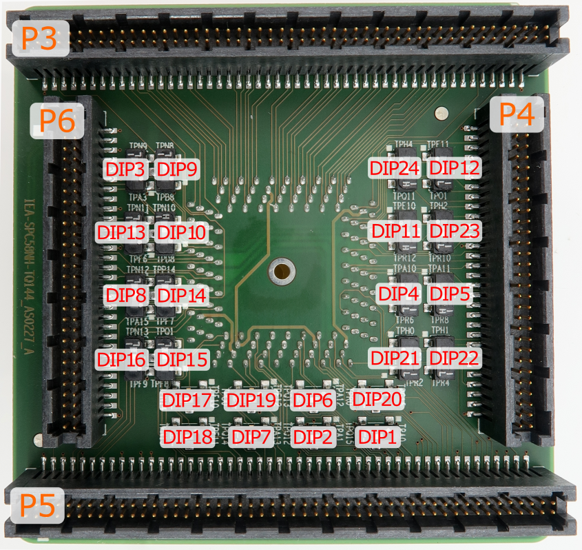
Conversion board IEA-SPC58NH-TQ144 consist of 24 DIP switches which define which alternate port is connected to a specific CPU pin.
With the original microcontroller in the QFP144 package this is configured through the application software. However when using the Emulation Adapter based on the BGA386 "superset" device, this configuration has to be performed manually through jumpers DIP1-DIP24 since for some reason each of the alternate ports is routed to an individual physical pin on the BGA386 device without the possibility for controlling routing by means of application software.
For example, with the original microcontroller in the QFP144 package, the application software can route either port PQ[15] or port PA[0] to pin 113. However, with the “superset” microcontroller in the BGA386 package, port PQ[15] is fixed connected to pin L22 and port PA[0] to pin B18. Hence with the Emulation Adapter you can define with the jumper DIP1 whether port PQ[15] or port PA[0] is routed to target pin 113 on the 144-pin conversion board.
|
Set all the DIPs accordingly to exactly match with your application software configuration. Any mismatch in configuration will yield application not operating properly! |
DIPs are by default in position 1-2 (enabled).
Following picture shows DIPs location on the top side of the conversion board:
DIP |
144-pin CPU Pin Number |
DIP position 1-2 (Default) |
DIP position 2-3 |
|---|---|---|---|
DIP1 |
113 |
PA[0] |
PQ[15] |
DIP2 |
110 |
PA[1] |
PQ[12] |
DIP3 |
68 |
PA[3] |
PN[9] |
DIP4 |
118 |
PA[10] |
PR[6] |
DIP5 |
119 |
PA[11] |
PR[8] |
DIP6 |
111 |
PA[12] |
PQ[13] |
DIP7 |
112 |
PA[13] |
PQ[14] |
DIP8 |
72 |
PA[15] |
PN[12] |
DIP9 |
67 |
PB[8] |
PN[8] |
DIP10 |
69 |
PD[8] |
PN[10] |
DIP11 |
121 |
PE[10] |
PR[12] |
DIP12 |
122 |
PE[11] |
PO[1] |
DIP13 |
70 |
PF[6] |
PN[11] |
DIP14 |
71 |
PF[7] |
PP[14] |
DIP15 |
73 |
PF[8] |
PQ[1] |
DIP16 |
74 |
PF[9] |
PN[13] |
DIP17 |
75 |
PF[10] |
PN[14] |
DIP18 |
76 |
PF[11] |
PN[15] |
DIP19 |
77 |
PF[12] |
PO[0] |
DIP20 |
114 |
PG[15] |
PR[0] |
DIP21 |
116 |
PH[0] |
PR[2] |
DIP22 |
117 |
PH[1] |
PR[4] |
DIP23 |
120 |
PH[2] |
PR[10] |
DIP24 |
123 |
PH[4] |
PQ[11] |


