Schematics
|
To view Emulation Adapter schematics, refer to Schematics . |
Below is a pinout of the four connectors P3-P6 on the bottom side of the emulation adapter:
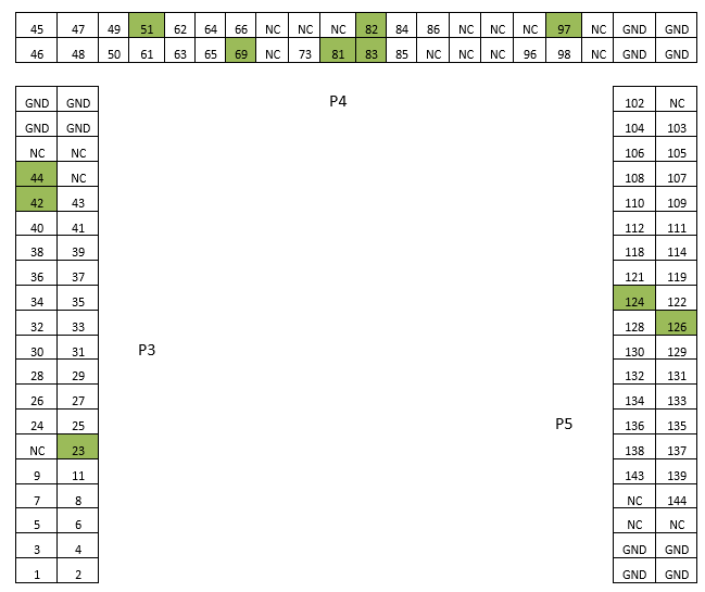
NC – Not Connected
Connectors expose only signals from the 144-pin emulation device, which exist on the 100-pin TC233 device. Green colored pins depict pins where pin numbering stops being continuously incremented by one.
Optionally, the target can be custom designed in a way directly providing connection for the emulation adapter through the P3, P4 and P5 connector. This way a high quality electrical and mechanical connection is established. Connectors being used on the emulation adapter side are TE connectivity female connectors, part number: 0-0104652-4 (40-pin connector). The target must feature male matching connectors. Contact iSYSTEM for technical details on the location of the three connectors.