Assembly
|
Watch out that the pin 1 position and alignment of all pins. Avoid disassembling and reassembling the hardware setup too frequently. |
|
Use the Surface Mount Technology (SMT) to solder the Solder parts to the target instead of the original microcontroller. We provide this soldering service on request. |
QFP Fixed
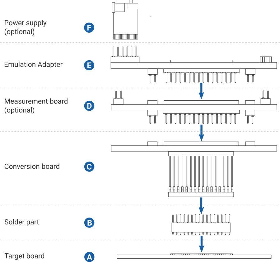
1. Solder the Solder part B on the Target A.
2. Assemble in order: Emulation Adapter E, optional Measurement board D, Conversion board C.
3. Connect the Conversion board to the Solder part B.
Slot screw
The Slot screw (30mm) is used to fix the Conversion board to the Solder part. The setup becomes mechanically more robust.Screw the Conversion board to the Solder part first, before the Emulation Adapter is attached on top and watch out not to break out the Solder part, e.g., if you accidentally hit the Emulation Adapter from the side.
QFP Flex
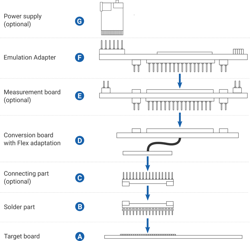
1. Solder the Solder part B on the target A. In the case of 0.4 mm pitch variant, assemble the Connecting part C on the Solder part.
2. Assemble in order: Emulation Adapter F, optional Measurement board E, Conversion board D.
3. Connect Conversion board's Flex adaptation D to the Solder part.
BGA
1. Solder the Solder part B on the Target A.
2. (optional, recommended) Connect Extender C to the Solder part B.
The Extender protects from damaging the Solder part if the Emulation Adapter setup is frequently assembled and disassembled. Be careful and gentle during this procedure because all parts of the setup are extremely sensitive, and pins can easily bend or even break in the worst-case scenario.
More Extenders can be stacked to gain height between the Emulation Adapter and the Target, if surrounding components so high that they prevent connecting the Emulation Adapter. Keep the number of Extenders C at minimum since every Extender degrades the signal integrity of the electrical signals.
3. Assemble in order: Emulation Adapter F, optional Measurement board E, Conversion board D.
4. Connect Conversion board D to:
• Solder part or
• Extender


