Setup and Configure Hardware
In this tutorial, you will learn how to connect and configure the iC7mini, iC5700 and iC5000 BlueBox with the embedded target.
The procedure of setting up BlueBox hardware and winIDEA software to start the embedded target development follows these basic steps:
•Connect the Grounding wire and set the BlueBox and Target to the same potential
•Connect the BlueBox and the Target
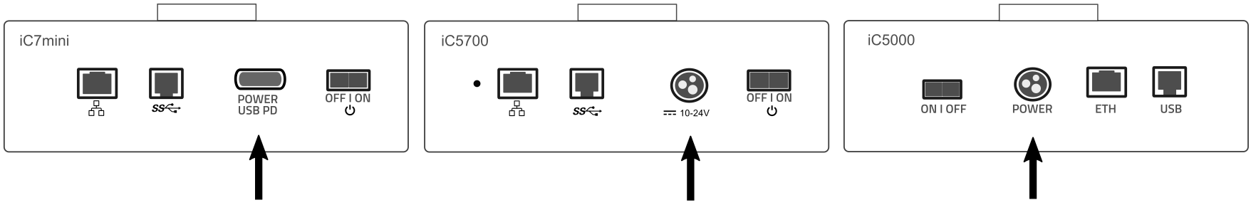
Connect the Power supply
Power connector is located on the rear side of the BlueBox.
|
Make sure the BlueBox is switched off. |

|
Connect the power supply cable. |

|
It is important to carefully push in (or pull out to disconnect) the iC5 power supply connector plastic sleeve into the BlueBox, as it features a locking mechanism. |
Connect the BlueBox and PC
BlueBox can be connected to a PC via:
•USB 2.0/3.0. - recommended - Fast connection, higher bandwidth
•TCP/IP - Remote operation, shared BlueBox hardware, Continuous Integration pipeline
|
To configure the TCP/IP connection, the BlueBox has to be temporarily connected to the PC via a USB cable. |
|
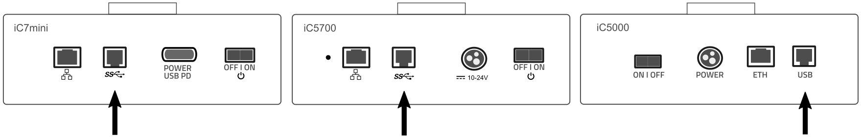
Connect via USB. |
Ethernet and the USB port may look similar. Make sure you connect the USB cable to the correct port.
|
(optional) Configure TCP/IP connection on the BlueBox and winIDEA side. |
•BlueBox - Via the Hardware / Debugger Hardware / Hardware Type / System Configuration. By default, the TCP/IP settings are obtained automatically from a DHCP server on the network. If such a server is not available, the settings can be set manually manually.
•winIDEA - It is possible to set IP address in three ways:
oSN number - Type in '#' and SN number, which can be found on the bottom of the BlueBox.
oAutomatic Discovery - Check the Use global discovery on UDP port 58371 and select suitable BlueBox via its serial number.
oManual Configuration - Enter IP address as entered in the BlueBox in the IP addr field.
Connect the Grounding wire and set the BlueBox and Target to the same potential
|
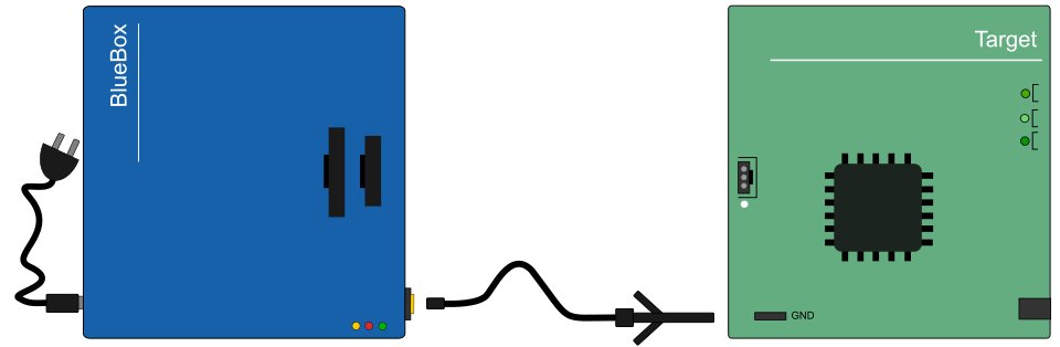
If the grounding wire is not connected, the ground potential difference between the BlueBox hardware and the Target can exceed well over 1000V even before any of the devices are powered up. This voltage difference is discharged over the BlueBox hardware and the Target, potentially leading to the destruction of electronic components within both the BlueBox hardware and the Target. |

|
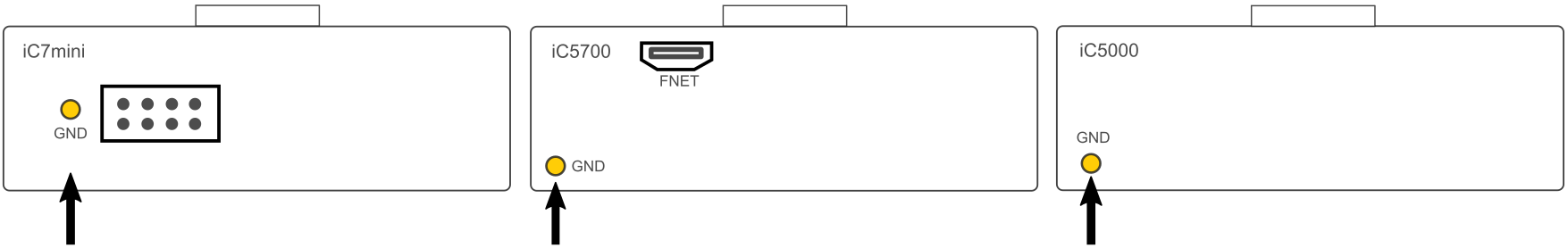
Connect the Grounding wire to the BlueBox. |
The grounding wire connector pin is located on the front panel of the BlueBox and is marked with "GND."
|
Locate ground potential (GND) on the Target and connect the test clip. |
Connect the BlueBox and the Target
Depending on the hardware configuration, the BlueBox can be connected to the Target via:
•Architecture-specific Debug Adapter
oOne ribbon cable detached from Debug Adapter (BlueBox iC7/iC5)
oTwo ribbon cables pre-attached to Debug Adapter (BlueBox iC5)
•Active Probe (iC5)
Via the Debug Adapter
The Debug Adapter is directly connected to the Target on one side and connects via the ribbon cable to the BlueBox connector located on top.
Push carefully (and remove) and PARALLEL both sides and listen for the “click”!
|
Connect the ribbon cable to the Debug Adapter. |
|
Connect the ribbon cable to the BlueBox connector(s). |
Debug Adapter, which comes with one detached ribbon cable, always connect to the #1 connector located on top of the BlueBox. The cable should face away from the BlueBox, with the red (edge) wire on the side of the #1 (and #2 - iC5 BlueBox) marking.
|
Connect the Debug Adapter to the Target. |

Pin 1 can be marked by dot next to the connector, number 1 marker or a triangle marker imprinted into the connector plastic, etc.

|
To disconnect, squeeze the two metal latches on the ribbon cables. |
|---|

Via Active Probe
The Active Probe is connected to the Target and the other side connects to the iC5700 FNet port via the FNet cable.
|
Connect Active Probe's FNet cable to the BlueBox FNet Port. |
|
Connect ribbon cable adapter(s) to Target Board. |
White dot is indicating pin one. Connectors also have a key and socket. Insert (and remove) the black connector parallel to the surface of the Target.

Via Active Probe Debug
The Active Probe Debug is connected to the Target and the other side connects to the iC5700 FNet port via the FNet cable.
|
Connect Active Probe's FNet cable to the BlueBox FNet Port. |
|
Connect ribbon cable adapter to the Active Probe Adapter. |
|
Connect the Active Probe Adapter to the Target. |
White dot is indicating pin one. Connectors also have a key and socket. Insert (and remove) the black connector parallel to the surface of the Target.

Via DAP/DAPE Active Probe
The Active Probe is connected to the iC5700 FNet port via the FNet cable and on the other side connects to the Target via:
•DAP connector - DAP interface provides access to the on-chip debug and the MCDS trace module.
•DAP and DAPE connector - DAPE interface provides access only to the on-chip MCDS trace module and increases the bandwidth of the trace channel toward the debugger.
You should design the PCB with the target debug connector(s) with the Keying Shroud since incorrect connection can cause damage to the hardware.
|
Connect the Active Probe's FNet cable to the BlueBox FNet port. |
|
Allocate the pin 1 on the Target and the ribbon cable connector. |
Pin 1 can be marked by dot next to the connector, number 1 marker or a triangle marker imprinted into the connector plastic, etc.
|
Push (and remove) the connector PARALLEL to the Target. |
|
(optional) Repeat steps 2. and 3. with the DAPE cable. |
|---|

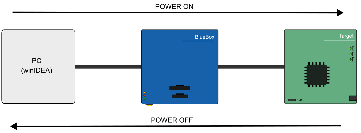
Power on the hardware
|
Power on the BlueBox. |
|
Power on the Target. |
When debugging is completed the hardware should be powered off in the reverse order.
More resources
•How to Connect BlueBox Hardware - Video Tutorial
•Power supply specifics - Hardware User Manuals
•USB driver issues - Knowledge Base
Next steps
•Architecture-specific settings