Power Probe measurement
In this topic:
Introduction
Power Probe with a shunt resistor enables measuring power consumption on target ECU, delivers precise measurements and offers different connection possibilities. A a quick detection of faults can be configured with the use of FNet Triggers. With this it’s quick and easy measuring power consumption on electronic circuit (e.g. evaluation board), which gets power over standard jack and external power supply.

Power consumption measurements
Picture below explains how the power consumption can be measured with two voltmeters respectively with two analog inputs in respect to the ADIO.
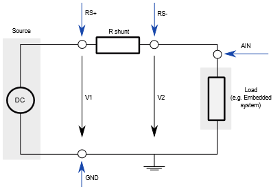
When measuring power, it is necessary that both the voltage and the current are measured at the same time, and that the relationship between these two is taken into account. The ways the voltage and current are measured have a great influence on the accuracy. The advantage of power measurement with a shunt resistor method is that it delivers precise measurements, it allows a quick detection and elimination of faults.
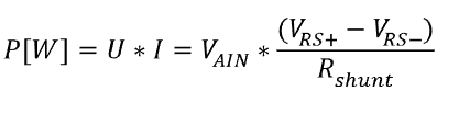
A shunt is a low-value resistor, connected in series to the load. The “current” through the shunt is measured by measuring the voltage drop on the shunt and the power is then calculated with formula:
If the target or just part of the electronic, where we want to measure the power along the application execution, provides already the shunt resistor in series to the load, user can connect necessary RS+, RS-, AIN and GND signals from the Power Sense connector to the target using provided clip wires.
Alternatively, TASKING provides Power Probe featuring already a shunt resistor and different connection possibilities. With this it’s quick and easy measuring power consumption on electronic circuit (e.g. evaluation board), which gets power over standard jack and external power supply.
Hardware configuration
Connecting with clip wires
For manual connection use set of clip wires which are delivered with the ADIO package.
|
Make sure that the embedded system and BlueBox are not powered. |
For voltage measurement
1. Connect GND from the Power Sense connector to the circuit ground of the embedded system.
2. Connect AIN input from the Power Sense connector to the supply voltage of the embedded system.
3. If the voltage is higher than 5V, use a suitable resistor divider. Enter the divider ratio as a Voltage/Multiply factor in winIDEA configuration dialog.
For current measurement
1. Connect GND from the Power Sense connector to the circuit ground of the embedded system.
2. Connect RS+ signal pin from the Power Sense connector to a high side of the shunt (see picture).
3. Connect RS- signal pin from the Power Sense connector to a low side of the shunt (see picture).
4. Specify the resistance of the R shunt resistor in winIDEA configuration dialog.
5. Switch ON BlueBox and embedded system power supply.
Picture depicts power measurement setup. Connect with clip wires where blue arrows indicate.
|
The full-scale shunt voltage range is 250mV (e.g. a 1Ω shunt resistor gives a current range of 250Ma). |
Full-scale Shunt Voltage |
Shunt Resistance |
Full-scale Current Range |
Shunt Power Dissipation |
|---|---|---|---|
250 mV |
1.0 Ω |
0.25 A |
0.063 W |
250 mV |
0.25 Ω |
1.00 A |
0.250 W |
250 mV |
0.10 Ω |
2.50 A |
0.625 W |
Power Probe
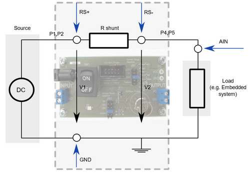
Power Probe (picture below) replaces wire connections described in section Connecting with clip wires.
It connects between a target power supply and a target board as shown on the next picture.
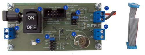
Connectors, Jumpers and a Switch
See this picture:
•P1 and P2 (marked 1 and 2) – Target power supply inputs. Use one or the other. Maximum voltage is 20V
•P3 (marked 3) – 10-pin IDC connector to connect the Power Probe with the ADIO using provided 10-pin ribon cabble
•P4 and P5 (marked 4 and 5) – Power supply output towards the target
•ST1 (marked 6) – BNC connector
•JB1 (marked 7) – Jumper block for selecting different shunt resistor
|
Excessive current will burn the resistors. Never set more than one jumper! Selected shunt resistors must handle the heat generated by the power dissipated on them. |
Three of the five available positions are populated with resistors:
Position |
Shunt Resistance |
Shunt Resistance including JB1 |
|---|---|---|
0.25 A |
1.00 Ohm |
1.00 Ohm |
1 A |
0.25 Ohm |
0.26 Ohm |
2.5 A |
0.10 Ohm |
0.11 Ohm |
The remaining two positions are available for a custom user setup with unpopulated resistors R5 and R6.
|
With lower shunt resistor values also the JB1 jumper resistance starts to play a role and may influence the measurement. This can be easily compensated by slightly increasing the shunt resistance value in the winIDEA setup dialog, by 0.01Ω, for example. |
•JB2 (marked 8) – Jumper block for selecting different voltage ranges.
Three of the five available positions are populated with resistor dividers:
Position |
Resistors |
Voltage Multiply (winIDEA configuration) |
|---|---|---|
5 V |
0/10 kΩ |
1 |
10 V |
10/10 kΩ |
2 |
20 V |
30/10 kΩ |
4 |
The remaining two positions are available for a custom user setup with unpopulated resistors R12 and R13. The lower part of the voltage divider is set by the R9 of 10kΩ.
•SW1 (marked 9 on the Picture 3) – Switch connecting/disconnecting P1/P2 connectors with P4/P5 connectors respectivelly “power on switch” for the embedded targeted connected to P4 or P5 connector.
•LD1 (marked 10 on the Picture 3) – LED indicator. Note that the LED needs a very small current to light and may glow because of a parasitic current flowing, for example, even when the emulator switched on and the target is off.
Connection procedure
1. Make sure that the embedded system and BlueBox are not powered.
2. Switch SW1 is in OFF position.
3. Configure 0.25 A, 1A or 2.5A current range on JB1 depending on the expected range of the measured current. To be on the safe side, you can start with 2.5A setting.
4. Configure 5, 10 or 20V voltage range on JB2 depending on the embedded target power supply range.
5. Connect power supply for the Embedded system to P1 or P2.
6. Connect Embedded system to P4 or P5.
7. Connect P3 to the ADIO Power Sense connector.
8. Power on BlueBox.
9. Power Embedded system by switching SW1 to ON position.
winIDEA Configuration
At this point you have:
•Successfully connected ADIO hardware
•Established debug connection
•Selected the current range according to the shunt resistor (JB1 jumper block) and voltage range depending on your target power supply range (JB2 jumper block) on the Power Probe.
|
Open Hardware / Options / FNet / ADIO / AIN. |

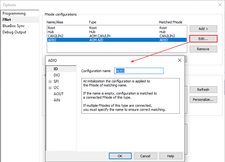
|
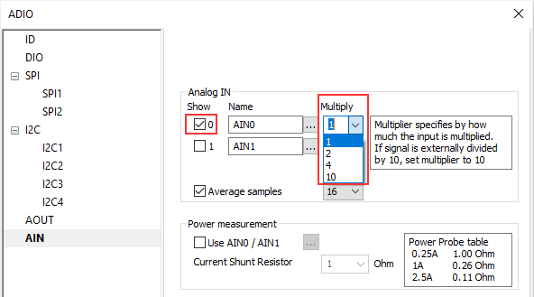
Configure AIN / Analog IN. |

1. Make sure only 0 (AIN 0) is checked.
2. From the Multiply drop-down menu select a multiplier for AIN0 based on position of JB2 (Jumper block for selecting different voltage ranges) on the Power Probe and the table below:
Position (V) |
Resistors (k/Ohm) |
Multiplier |
|---|---|---|
5 |
0 / 10 |
1 |
10 |
10 / 10 |
2 |
20 |
30 / 10 |
4 |
Select multiplier 10 if the signal is externally divided by 10.
|
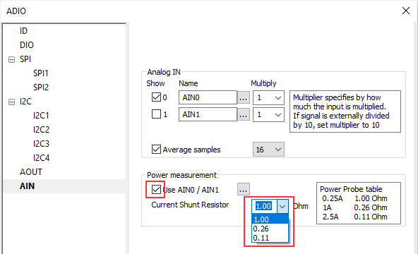
Configure AIN / Power measurement. |

1. Check Use AIN0 / AIN1.
2. From the Current Shunt Resistor drop-down menu select a shunt resistor based on position of JB1 (Jumper block for selecting current range according to the shunt resistor) on the Power Probe.
and the table on the right side in winIDEA:
Current (A) |
Shunt Resistor (Ohm) |
|---|---|
0.25 |
1.00 |
1 |
0.26 |
2.5 |
0.11 |
For custom shunt resistors type in the value.
More resources
•ADIO Add-on module - Hardware User Manual
• HIL Monitor - Plugin for output signals manual manipulation and display of the input signals state