Debug Adapter
The Debug Adapter is directly connected to the embedded Target and the other side connects via the ribbon cable to the iC5000/iC5700 Debug and Trace Module (DTM).
|
Microcontroller development boards have different debug connectors, therefore we have a range of Debug Adapters suitable for everything from simple debug through to full trace interfaces. More information about iSYSTEM Debug Adapter is available in the User Manual. |
Debug Adapters (delivered along with the BlueBox) use:
- One ribbon cable detached from Debug Adapter or
- Two ribbon cables pre-attached to Debug Adapter
|
The connector has a locking mechanism. Push carefully (and remove) and PARALLEL both sides and listen for the “click”! |

Connecting one flat ribbon cable
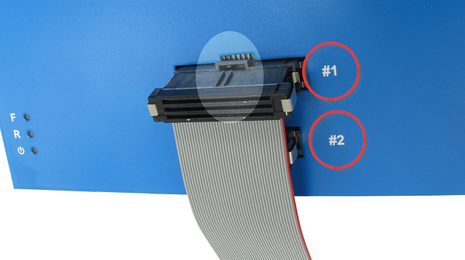
Debug Adapters, which come with a detached ribbon cable, connect always to DTM #1 connector located on top of the BlueBox.
|
Connect the ribbon cable to the DTM #1 connector. |

The cable should be facing away from the BlueBox with the red (edge) wire on the side of the DTM #1 marking. Align the orientation key/notch of the cable connector with the notch on the BlueBox connector marked with #1. Press the cable connector carefully straight down until the latches lock.

|
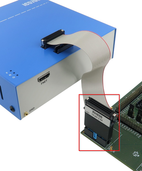
Connect the Debug Adapter to the other side of the ribbon cable. |

Align the orientation key/notch on the Debug Adapter connector with the connector on the flat ribbon cable. Press the cable carefully straight down until the latches lock.
|
Connect the Debug Adapter to the Target |

Refer to the chapter Connect the Debug Adapter to the Target.
Connecting two flat ribbon cables
If the Debug Adapter features two flat ribbon cables, it comes fixedly connected.
|
Connect the ribbon cable to the DTM #2 connector. |
The cable should be facing away from the BlueBox with the red (edge) wire on the side of the DTM #2 marking. Align the orientation key/notch of the cable connector with the notch on the BlueBox connector marked with #2. Press the cable connector carefully straight down until the latches lock.
|
Connect the ribbon cable to the DTM #1 connector. |
The cable should be facing away from the BlueBox with the red (edge) wire on the side of the DTM #1 marking. Align the orientation key/notch of the cable connector with the notch on the BlueBox connector marked with #1. Press the cable connector carefully straight down until the latches lock.
|
Connect the Debug Adapter to the Target |
Refer to the chapter Connect the Debug Adapter to the Target.
Connecting Debug Adapter and Target
|
The connector has a locking mechanism. Push carefully (and remove) and PARALLEL both sides and listen for the “click”! |
 1. Ensure that both the BlueBox and the Target are not powered 2. Ensure that the Grounding Wire is securely connected 3. Connect the Debug Adapter to the Target
Pin 1 can the Target can be marked by:
If the target connector doesn't provide a key pin or a key notch, make sure pin 1 is properly identified on the Debug Adapter and the Target since a mistake could damage the hardware. |
Disconnecting guidelines
In order to disconnect the flat ribbon cables from the DTM #1 or #2 connector, squeeze the two metal latches on the cable connector from the side and pull the cable from the DTM #1 respectively #2 connector.